- Home / Solutions In HVAC / Shell-and-tube replacement with only dimensional data
Shell-and-tube replacement with only dimensional data
Contents/ Mục Lục
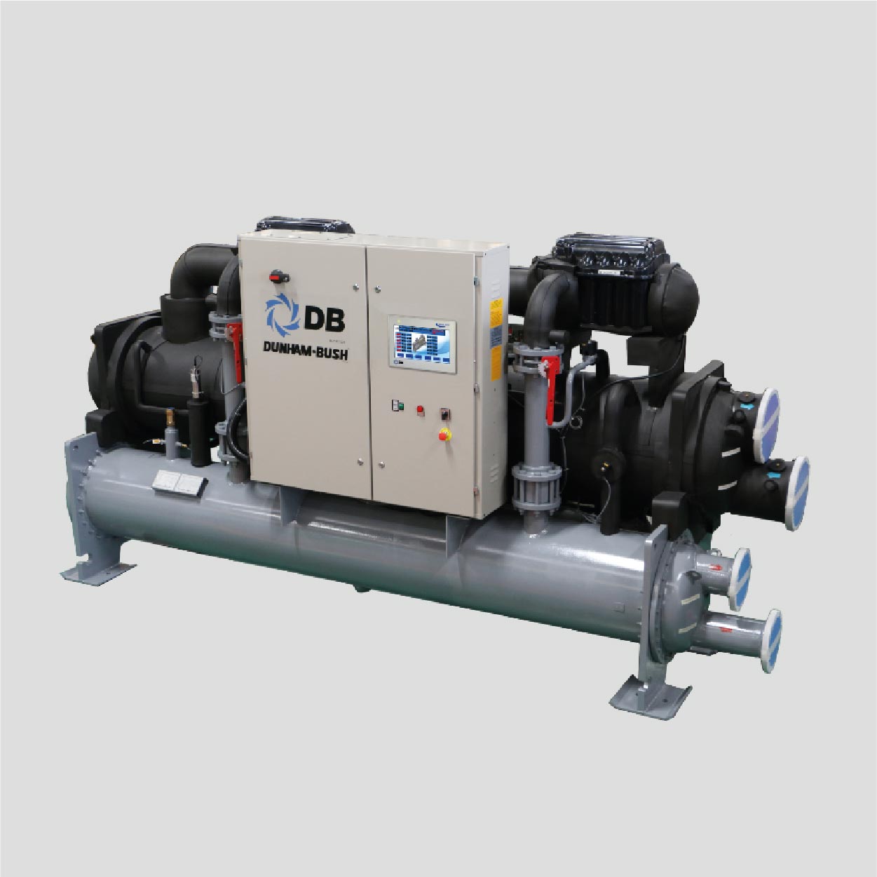
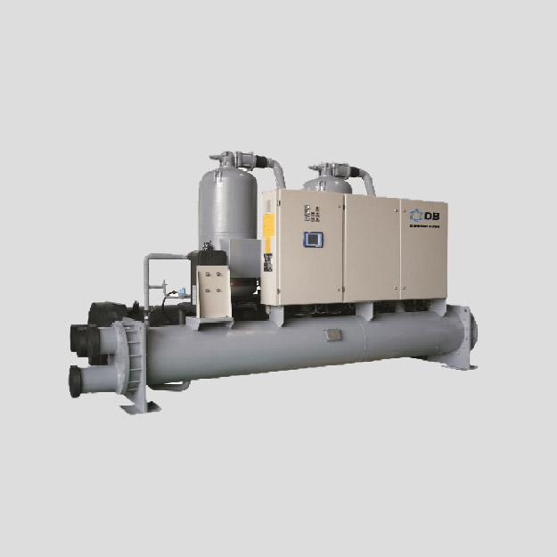
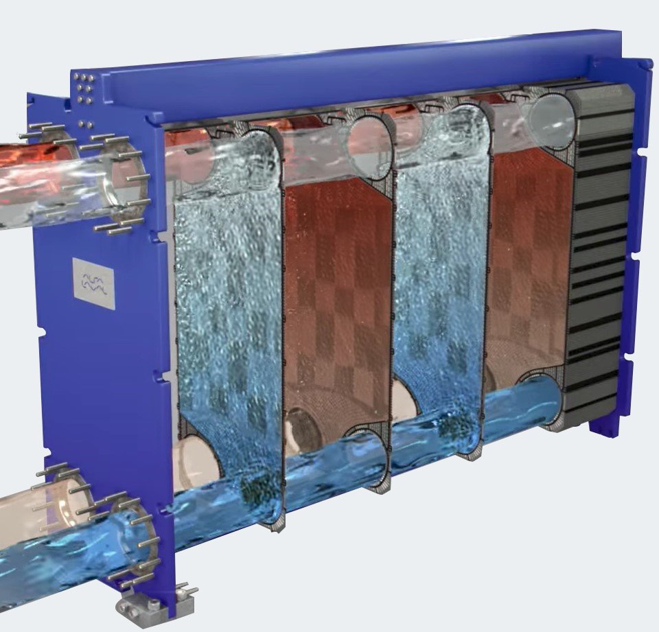
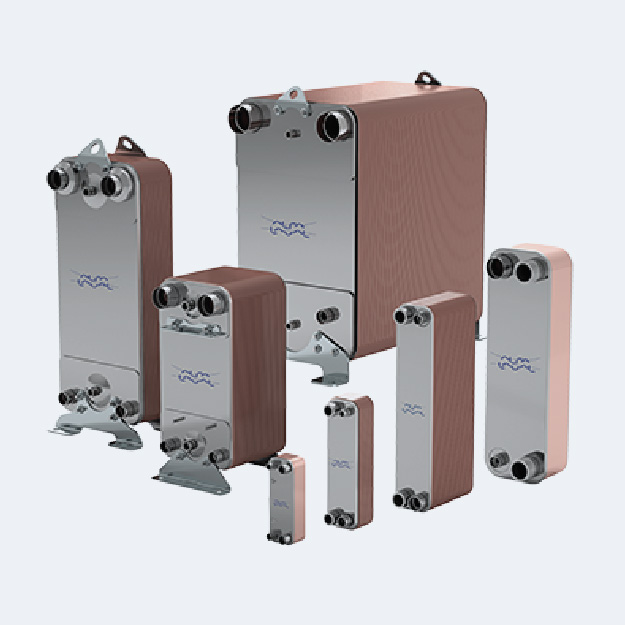
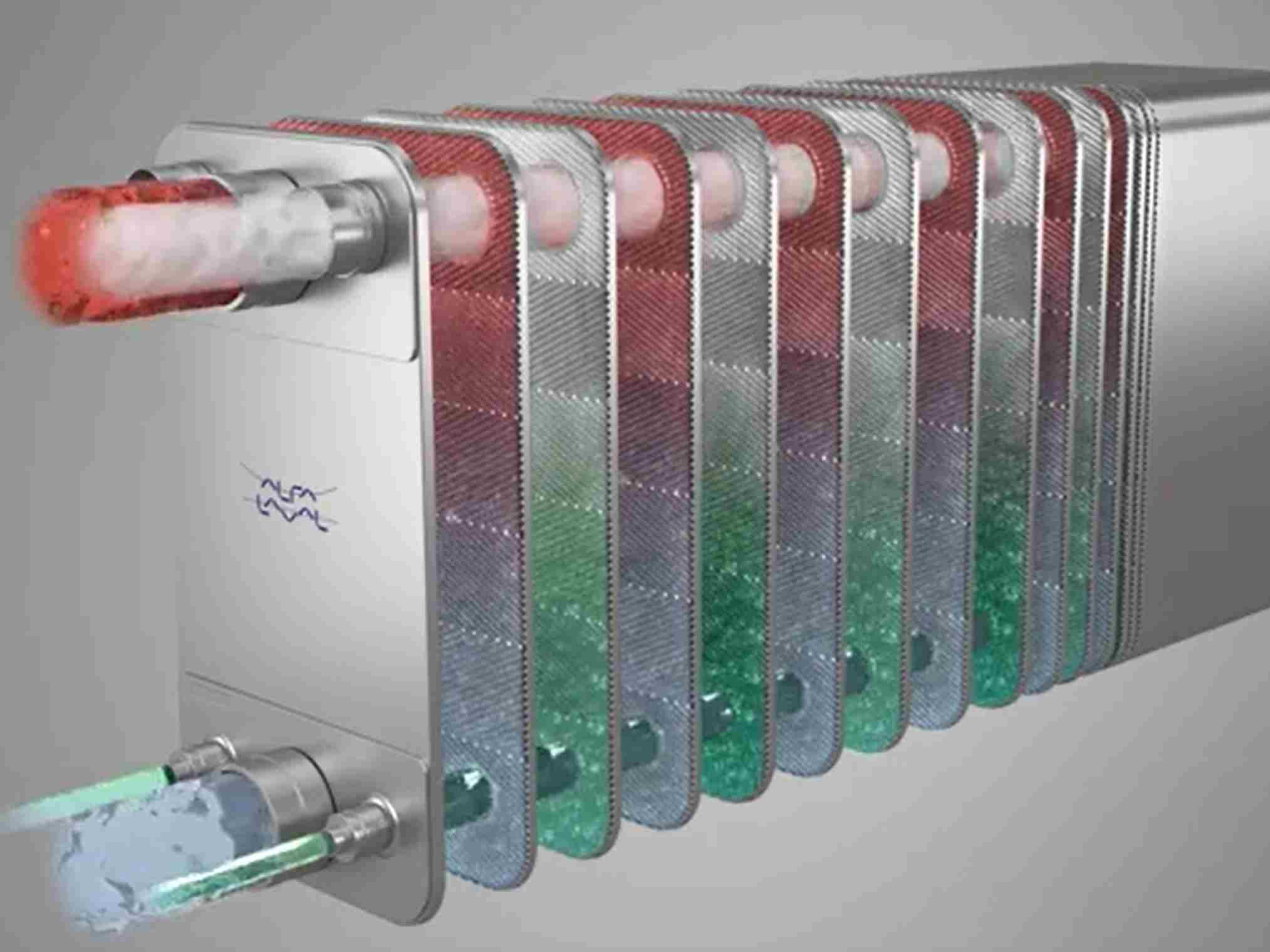
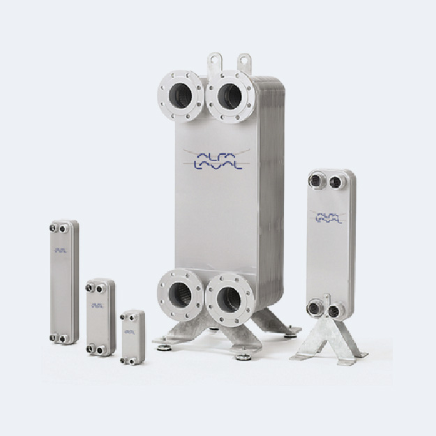
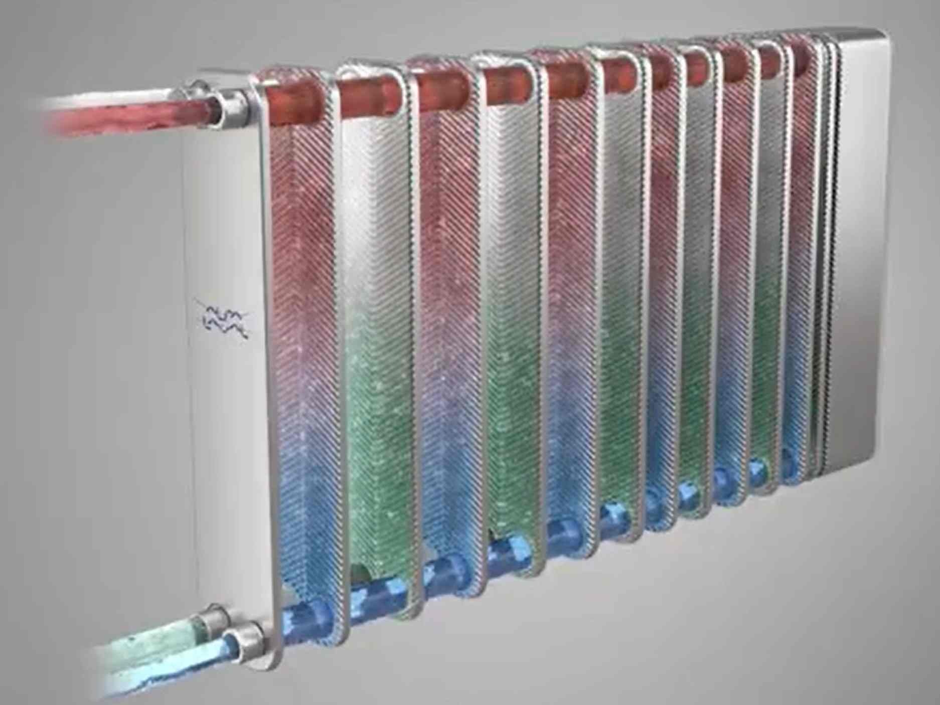
Shell & Tube Heat Exchangers have been widely used for a long time across various industries. They offer several advantages, such as simple fabrication using readily available materials, the ability to be manufactured in any size, and the capacity to withstand all temperature and pressure conditions. However, they also have some limitations, which can be overcome by replacing them with plate heat exchangers.
Structure of Shell & Tube Heat Exchangers
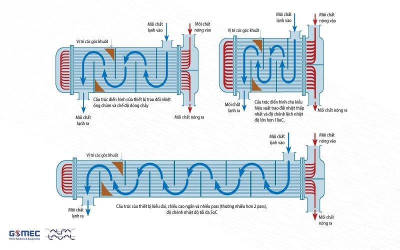
A typical structure of a Shell & Tube Heat Exchanger consists of a short length with an increased height, which is commonly found in applications requiring low thermal efficiency and a temperature difference of over 10°C. These exchangers are often used in oil or steam cooling applications, featuring large tube diameters and a single-pass design.
For applications that demand high heat transfer efficiency with a temperature difference of around 5°C (the maximum achievable by shell & tube heat exchangers), the structure is elongated with a reduced height and multiple passes (typically more than two).
The shell of the exchanger is usually made from carbon steel with flanged connections at both ends. The tubes are made from standard materials such as copper, carbon steel, or stainless steel (inox), with diameters conforming to inch-based standards (e.g., ¼”, ½”, ¾”). Tubes are typically arranged in a triangular pattern for optimal heat transfer within a given space.
Limitations of Shell & Tube Heat Exchangers
- Low fluid velocity within the exchanger can lead to clogging or fouling, reducing efficiency.
- Incomplete counterflow heat exchange, as certain blind spots limit effective heat transfer, resulting in low efficiency.
- Bulky size and large footprint, making installation, maintenance, and servicing difficult. Additionally, the large shell surface area leads to significant heat loss.
On the shell side, clean fluids such as gas or steam are preferred due to cleaning difficulties, while the tube side is used for fouling-prone fluids like water, as the tubes can be cleaned manually. However, complete maintenance and cleaning of the exchanger remain challenging, leading to increasing fouling deposits and declining performance over time.
Shell & Tube Heat Exchangers
Why Replace Shell & Tube Heat Exchangers with Plate Heat Exchangers?
The main reason for the lower efficiency of Shell & Tube Heat Exchangers is their incomplete counterflow and inability to create turbulent flow. The temperature difference across most Shell & Tube Heat Exchangers is about 5°C, whereas plate heat exchangers offer much higher efficiency, achieving a temperature difference as low as 0.5 – 1°C.
Optimized Counterflow in Alfa Laval Plate Heat Exchangers
Alfa Laval’s plate heat exchanger (GPHE) design ensures 100% counterflow, optimizing heat transfer efficiency. In typical applications, the heat transfer area comparison between GPHE and Shell & Tube Heat Exchangers (S&T) is as follows:
Fluid Type | Heat Transfer Area (m²) |
Water/Water | GPHE = S&T / 4 |
Oil/Water | GPHE = S&T / 2 |
Steam/Water | GPHE = S&T |
This demonstrates that GPHE requires significantly less heat transfer area than Shell & Tube Heat Exchangers, leading to:
- Reduced installation space
- Lower operational and maintenance costs due to easier cleaning
- Minimized heat loss to the environment
By switching to plate heat exchangers, industries can enhance efficiency, save space, and reduce energy consumption, making them the superior choice for modern heat exchange applications.
- project@gomec.vn
- Hotline & Zalo 0379 586 886
- (+84) 024 3200 8920
- Gomec Vietnam
- Gomec Vietnam


Leave a Reply